


Overview
The vector table in Cortex-M3 starts at number 0.In the table, the addresses (vectors) of exception handlers and ISRs (interrupt service routines) are described.In other Arm processors such as Arm7, the method is to write an instruction, execute the instruction and jump to the destination address.On the other hand, in Cortex-M3, there is no need to write an instruction, and the handler will automatically send you to the destination address if you write the destination address.
Table size (words) = number of IRQ inputs + 16. The minimum size (1 IRQ) is 17 words and the maximum size (240 IRQ) is 256 words.
In a typical microcontroller, the minimum address part (0) of the vector table is assigned a reset vector, but in Cortex-M3, the initial value of the main stack (SP_main) is assigned.Therefore, it is not necessary to initialize SP_main in the initial routine of the software.After resetting the microcontroller, the value of SP_main is automatically stored in R13 (SP).
The vectors from 0x00 to 0x3C are for Cortex-M3, and the vectors from 0x40 onwards are assigned to the microcontroller’s peripheral functions or interrupts from outside.
| address | vector |
|---|---|
| 0x00 | Initial value of SP_main |
| 0x04 | reset |
| 0x08 | NMI |
| 0x0C | hard fault |
| 0x10 | memory management |
| 0x14 | bus fault |
| 0x18 | Dosage Fault |
| 0x1C-0x28 | Reserved |
| 0x2C | SVCall |
| 0x30 | debug monitor |
| 0x34 | Reserved |
| 0x38 | PendSV |
| 0x3C | Systick |
| 0x40 | IRQ0 |
| … | ~ IRQs |
Moving the Vector Table
Some microcontrollers have separate code area and data area on the memory map, but with Cortex-M3, code can be written anywhere on the memory map and executed.In other words, it is possible to write a program in the RAM area and execute it.
When a microcontroller with Cortex-M3 is equipped with a function to stop Flash and reduce power consumption, Flash can be stopped and code on RAM and other memories (EEPROM, etc.) can be executed.However, in this case, if the vector address is on the Flash, the interrupt cannot be executed.So, the Cortex-M3 vector table is movable.
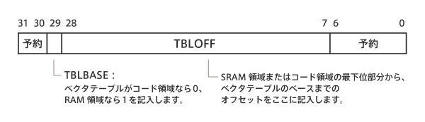
To move the vector table, use the vector table offset register.The vector table offset register indicates where the vector table is located in the code area or SRAM area.
After reset, the default value is 0 (code area).TBLBASE in the register indicates whether the vector table is in the code area or the RAM area, and TBLOFF indicates the offset from the SRAM area or the lowest part of the code area.
When setting the position of the vector table, the number of exceptions must be taken into account when setting it.This means that the minimum alignment that can use up to 16 interrupts is 32 words.If the number of interrupts is higher, they should be rounded up to the next power of two and taken into account.For example, if 21 interrupts are needed, the table size is 37 words and the next power of 2 is 64, so the alignment needs to be 64 word bounded.
Vector table offset register

“もっと見る” カテゴリーなし

Mbed TLS overview and features
In this article, I'd like to discuss Mbed TLS, which I've touched on a few times in the past, Transport …
What is an “IoT device development platform”?
I started using Mbed because I wanted a microcontroller board that could connect natively to the Internet. At that time, …
Mbed OS overview and features
In this article, I would like to write about one of the components of Arm Mbed, and probably the most …